1. Wire Metallurgy: Elasticity, Work Hardening, and Pliers Notching
Orthodontic wires used in removable appliance fabrication are predominantly cold-worked austenitic stainless steel (18/8 composition: 18% chromium, 8% nickel). The clinical success of a spring or clasp relies on its modulus of elasticity, yield strength, and springback characteristics. As wire is bent repeatedly at the bench, internal dislocations in the crystalline lattice multiply and pile up, causing work hardening.
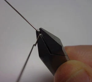
While moderate work hardening increases the proportional limit, excessive manipulation makes the wire brittle, leading to premature fatigue failure in the mouth. Technicians must bend wire around the rounded beak of Adams or universal pliers (such as No. 64 or 65) rather than sharp, square corners.
Surface notching caused by serrated or worn plier beaks acts as a stress concentration point. Under intraoral masticatory cycling, micro-cracks propagate rapidly from these surface defects, resulting in sudden clasp fracture at the crib bridge or arrowhead junction.
Beyond stainless steel, technicians increasingly encounter nickel-titanium (NiTi) and beta-titanium (TMA) alloys referred to them for auxiliary springs or sectional archwire repairs. These alloys exhibit superelastic behaviour rather than simple elastic recovery, meaning they can be deformed substantially and still return to their original shape at body temperature without the same work-hardening penalty as stainless steel — but they cannot be reliably re-bent cold on the bench in the way stainless steel can, and attempts to do so with standard pliers commonly produce a permanent kink rather than a smooth curve.
2. Digital Design in the Orthodontic Laboratory: Scanning, CAD Setwork, and Indirect Bonding Trays
Many orthodontic cases now enter the laboratory as an intraoral scan (STL/PLY file) rather than an alginate or PVS impression, particularly where the referring practice already scans routinely for aligner or retainer work. This removes distortion risks associated with alginate syneresis and imbibition during transit, and it allows the laboratory to archive the case digitally rather than maintaining a physical study model store — a meaningful practical benefit given that plaster archives are bulky, fragile, and vulnerable to breakage or loss over the years a record must be retained.
Digital setwork software allows the technician or clinician to virtually segment individual teeth from the scanned arch and reposition them to a proposed final occlusion. This "digital setup" is not merely a visualisation aid: it is the master reference from which downstream manufacturing steps — printed working models, indirect bonding trays, and increasingly robotically bent archwires — are all derived, so any error introduced at the segmentation or repositioning stage propagates through every subsequent product.
An indirect bonding tray is a clear, close-fitting appliance manufactured (typically by vacuum-forming over a 3D-printed model of the digital setup, or occasionally directly 3D-printed) that carries brackets in laboratory-verified positions so the clinician can bond an entire arch in a single clinical seating, in one recorded transfer, rather than positioning each bracket freehand tooth by tooth. This shifts a considerable amount of bracket-positioning precision and responsibility from the chairside to the laboratory bench, and the technician must verify bracket base adaptation and tray seating on the printed model meticulously before dispatch, since an error here is otherwise bonded directly into the patient's mouth.
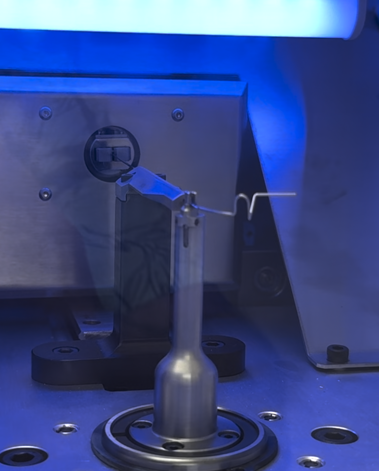
A related and genuinely advanced development is CAD/robotically bent archwire manufacture. Once a digital setup exists, dedicated wire-bending robots can form a stainless steel or NiTi archwire to a highly repeatable, software-calculated geometry customised to the patient's planned tooth positions, rather than a generic pre-formed arch shape adjusted by hand. This does not remove the metallurgical principles covered in Section 1 — springback still has to be compensated for — but it moves that compensation into calibrated machine parameters rather than clinical judgement at the pliers, which can improve consistency across a large caseload, provided the robot is properly calibrated and maintained and the laboratory understands that a robotically-formed wire is only as accurate as the digital setup it was derived from.
3. Retentive & Active Components
The Adams clasp remains the standard for anchorage on permanent molars and premolars. The arrowheads must engage the mesio-buccal and disto-buccal cervical undercuts at the junction of the crown and gingival margin, angled at 45° to the long axis of the tooth. If the bridge of the clasp is placed too close to the buccal surface, it prevents the clinician from adjusting the arrowheads chairside.
Active springs deliver light, continuous physiological forces (typically 25g to 50g for single-rooted anterior teeth). Finger springs and Z-springs utilize a coil (helix) to increase the effective length of the wire without increasing appliance bulk. Increasing wire length markedly increases flexibility and reduces the load-deflection rate according to the formula: Deflection ∝ L³ / d⁴.
Because force is inversely proportional to the fourth power of diameter ($d^4$), a subtle increase in wire gauge (e.g., from 0.5mm to 0.6mm) nearly doubles the stiffness and delivered force, risking root resorption or appliance displacement if not compensated by design.
Where a case has been digitally set up, some laboratories now use simple beam-bending calculators or CAD plug-ins to model the expected load-deflection behaviour of a proposed spring design before it is bent, checking the planned wire diameter and coil configuration against the target force range at the design stage rather than relying solely on bench experience. This is a useful cross-check, but it does not replace the technician's hands-on judgement of how the spring will actually behave once seated against soft tissue and adjacent acrylic.
4. Acrylic Baseplate Processing: Minimising Porosity and Monomer Leach
Removable appliance baseplates are commonly constructed using autopolymerising (cold-cure) PMMA via the "salt and pepper" (spray-on) or slurry technique. Achieving maximum density and aesthetic clarity demands precise control over the polymerisation exotherm and monomer volatility.
Gaseous porosity occurs when the highly volatile methyl methacrylate monomer (boiling point 100.8°C) vaporises due to an uncontrolled chemical exotherm or rapid heat application. Contraction porosity results from insufficient monomer wetting, leaving dry polymer beads within the matrix.
To ensure full conversion and eliminate voids, freshly sprayed baseplates must be immediately transferred to a temperature-controlled hydroflask (pressure vessel) maintained at 40°C to 45°C under 2.0 to 2.5 bar (30–35 psi) of air pressure for a minimum of 15 to 20 minutes. This suppresses monomer boiling, minimizes residual monomer leaching, and prevents oral mucosal irritation.
Where the working model itself has been 3D-printed from a digital scan rather than poured in plaster, an additional check is required: some photopolymer printing resins are porous or slightly hygroscopic at a microscopic level compared with dental stone, and can absorb or release volatiles differently during the acrylic exotherm. It is good practice to seal a printed model with a manufacturer-approved model sealant before applying separating medium, to avoid an inconsistent basal surface finish on the finished baseplate.
5. Retention Appliances: Vacuum-Formed, Pressure-Formed, and CAD/Directly Printed Retainers
Thermoplastic retainers (polyethylene terephthalate glycol / PETG or polyurethane) have become the predominant post-treatment retention appliance due to rapid turnaround and high patient compliance. However, thermal degradation during thermoforming alters polymer chain length, leading to early wear or stress cracking if heated unevenly.
A distinction worth making explicitly is between vacuum-forming and true positive pressure-forming. Vacuum-forming draws a softened sheet down onto the model using negative pressure alone and can leave thin, unevenly adapted material over sharp cusp tips or deep undercuts, since suction alone struggles to fully seat the sheet into abrupt topography. Pressure-forming units apply substantially higher positive air pressure (commonly 6 to 8 bar) from above the softened sheet, forcing more uniform material thickness into fine detail and undercuts — a meaningful advantage for cases with pronounced cuspal anatomy, attachments, or clear aligner-style retainers designed with tooth movement ramps built in.
A genuinely advanced alternative now available to some laboratories is the directly 3D-printed retainer, produced from a biocompatible, Class IIa-rated photopolymer resin without any thermoforming step at all: the retainer geometry is designed directly in CAD from the digital model and printed as a finished shape, then post-cured and lightly polished. This removes sheet-thickness variability and thermoforming distortion entirely, and because the design file is stored digitally, a lost or broken retainer can in principle be re-printed on demand without recalling the patient for a fresh impression or keeping a physical model in storage — directly building on the digital archiving point raised in Section 2.
Directly printed retainers are not yet a wholesale replacement for thermoformed PETG in every case, however: printed resin surface finish typically requires more meticulous polishing to match the optical clarity and smoothness of a thermoformed sheet, wall thickness is fixed by the design file rather than adjustable at the chair, and the laboratory must ensure the specific resin and printer/post-cure combination in use is properly validated for long-term intraoral contact under the Medical Devices Regulations before it is offered as a routine, dispensed clinical option.
6. UK Compliance & Dispatch for Removable and Retention Appliances
The technician must trim VFR margins scalloped 0.5mm above the gingival margin or straight across the gingival crest, ensuring all interdental flash is polished smooth with specialized silicone points to prevent gingival impingement, regardless of whether the appliance was thermoformed or directly printed.
Under UK MDR regulations, every custom orthodontic appliance requires a compliant Statement of Conformity and work ticket specifying material batches, plastic sheet thickness (e.g., 1.0mm vs 1.5mm) or printed resin batch and layer thickness, and wire compositions. The ticket must record that the device is custom-made exclusively for the named patient.
Where a digital workflow has been used — intraoral scan, CAD setup, indirect bonding tray, robotically bent archwire, or directly printed retainer — it is good practice to also retain the source design file and a record of the software version and, where applicable, the printer/resin combination used, alongside the physical work ticket. This is not yet universally a strict statutory field for every appliance type, but it materially strengthens traceability if a fault or complaint arises later and the case needs to be reviewed or the appliance remanufactured.