1. Digital Impression Capture: Intraoral Scanning, Scan Bodies, and the Case for Conventional Impressions
The implant workflow now typically begins chairside, not on the bench. Intraoral scanners (IOS) capture the arch as a sequence of optical frames — using confocal, active/structured light, or dual-focal depth techniques depending on manufacturer — which are stitched in real time into a continuous 3D mesh. For dentate quadrants this stitching is highly reliable because enamel line angles and interproximal contacts provide abundant, stable reference geometry for the software to lock onto.
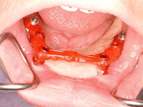
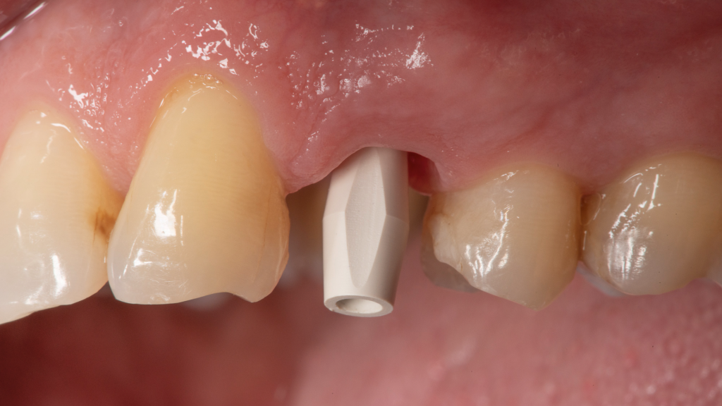
Implant sites present a very different problem. A healed edentulous ridge, a wide healing abutment, or a scalloped soft-tissue collar offers few unique landmarks, so the scanner can drift or "double" the surface across a pass. This is precisely why a scan body is screwed into the implant platform before scanning: its geometric features (flats, notches, or an asymmetric collar) give the software a single, unambiguous, high-contrast reference it can triangulate against, from which the exact 3D position and rotational orientation of the implant platform is mathematically derived and exported to the design software as a known coordinate.
Scan bodies fall broadly into two families. Proprietary (OEM) scan bodies are manufactured and verified by the implant company against their own connection tolerances and are generally the most trustworthy for anti-rotational platforms. Universal/generic scan bodies fit a wide range of connections via interchangeable bases but introduce an additional machining tolerance stack-up at the interface — a small but real source of positional error that increases with the number of implants being splinted.
Conventional elastomeric impressions (open-tray with a pick-up coping, or closed-tray) remain far from obsolete. They are still frequently the more predictable choice for long-span, multi-implant full-arch cases where cumulative digital stitching error across the arch can exceed the trueness achievable with a verified open-tray splinted impression using a rigid, luted, or 3D-printed verification jig. Deep, narrow, or heavily undercut sites, patients with a strong gag reflex intolerant of prolonged scanning, and situations where soft-tissue retraction is difficult to sustain optically can all favour a conventional approach, or a hybrid technique combining a physical verification jig with a digital scan.
Regardless of modality, trueness (how close the capture is to the real geometry) and precision (how repeatable the capture is) must both be considered. A scan can be highly precise — reproducible run to run — while still being systematically untrue if the scan body seating, calibration, or stitching pattern is flawed. The laboratory should never assume an incoming STL is dimensionally correct without sanity-checking implant spacing and angulation against the case photographs or a poured verification model where one exists.
2. Benchtop Scanning and Manufacturing Method Selection: Milling versus Additive Manufacture
Where a conventional impression or a physical master model is still produced, the laboratory digitises it using a benchtop (desktop) scanner rather than an IOS. These structured-light or laser scanners operate in a controlled, static environment with the model rotated on a calibrated stage, which removes the patient-movement and saliva/blood interference variables inherent to intraoral scanning and typically achieves superior trueness across long spans — one of the main reasons a "scan-the-model" step is still specified for complex full-arch cases even when the original impression at chair was digital.
Once a validated digital model exists — whether from IOS, benchtop scanning of a poured cast, or benchtop scanning of a physical verification jig — the technician designs the substructure in CAD and must then select a manufacturing route. The two dominant routes are subtractive milling and additive (3D printing) manufacture, and the choice is rarely interchangeable; each suits different materials and clinical demands.
Subtractive milling remains the standard for definitive zirconia and titanium implant frameworks. Pre-sintered or fully-sintered zirconia blanks, and pre-fabricated wrought titanium blanks, are cut using 4- or 5-axis dry or wet-milling units. Milling from a homogeneous, factory-certified, isotropic blank gives excellent, well-characterised mechanical properties and dimensional predictability, but it is inherently wasteful of material, tool-wear sensitive on titanium, and geometrically constrained by bur diameter — sharp internal line angles and very fine screw-access chimneys can be difficult or impossible to mill cleanly.
Additive manufacture — principally DLP (digital light processing) and SLA (stereolithography) resin printing for provisional and surgical-guide work, and metal additive routes such as DMLS/SLM (direct metal laser sintering / selective laser melting) for cobalt-chromium or titanium substructures — builds the part layer by layer from a digital file. This allows complex internal geometries, multiple-unit frameworks in a single build, and material efficiency that milling cannot match. However, additively manufactured metal frameworks require post-processing (support removal, stress-relief heat treatment, and often re-milling of the intaglio/interface surfaces to achieve implant-level passive fit) because as-built layer accuracy at the critical implant interface is rarely adequate on its own.
For UK laboratories, material choice under the Medical Devices Regulations governs which route is appropriate: a manufacturing process must be validated for the specific material and indication being produced, and mixing an unvalidated printer/resin/post-cure combination for a definitive, load-bearing implant substructure carries real regulatory and clinical risk. Provisional and diagnostic work is comparatively well suited to additive manufacture; long-term definitive implant frameworks in the UK market are still, at present, predominantly milled.
3. Screw-Retained vs. Cement-Retained: Biomechanical & Biological Realities
In contemporary UK dental technology, screw-retained restorations represent the primary gold standard for both single units and multi-unit bridgework. The driving factor is biological: subgingival extrusion of excess luting cement remains one of the leading aetiological triggers for peri-implant mucositis and subsequent peri-implantitis. Because the peri-implant soft-tissue seal lacks the Sharpey's fibre attachment found around natural teeth, extruded resin or glass ionomer readily migrates down the titanium surface, establishing an intractable bacterial reservoir.
Screw retention provides predictable retrievability for maintenance, screw tightening, hygiene access, or ceramic repair without damaging the underlying fixture. However, screw retention historically required ideal fixture angulation. Where an implant fixture emerges through the facial aspect of an anterior tooth or the incisal edge, direct screw access compromises aesthetics.
Angulated Screw Channel (ASC) systems now allow the technician to redirect the access channel by up to 25° to 30° within the digital design environment. Using specialised hexalobular/ball-head drivers, full clamping torque can be delivered off-axis. Cement-retained restorations are now strictly reserved for situations where fixture angulation exceeds ASC limits (>30°), or where extreme interocclusal clearance prevents adequate screw channel chimney height.
It is worth noting that the choice is rarely made in isolation from the digital planning stage covered above: an ASC design decision is generally taken at the CAD implant-planning step, once the scan body export confirms the true angulation of the fixture relative to the intended occlusal table, rather than discovered as a surprise once the framework reaches try-in.
4. Preload, Clamping Force, and the Mechanics of Screw Loosening
Screw loosening is rarely a spontaneous event; it is the direct mechanical consequence of inadequate preload, non-passive framework fit, or excessive dynamic lateral loading. When an abutment screw is torqued, the rotational force translates down the helical thread, stretching the screw elastically along its long axis like a stiff spring. This tension generates the clamping force that binds the abutment firmly to the implant connection.
Crucially, between 80% and 90% of the torque applied by the clinician is lost to friction between the mating screw threads and the internal fixture connection; only 10% to 20% is actually converted into useful clamping preload. Surface-treated screws (e.g., carbon-coated or Gold-Tite) alter the friction coefficient, delivering significantly higher preload at standard torque values compared to plain titanium screws.
Settling effect (embedment relaxation) occurs as microscopic surface asperities on freshly machined threads flatten under initial loading. In the laboratory, running a screw in and out of an analogue repeatedly wears and galls the threads. If that same worn screw is subsequently delivered for clinical insertion, the achieved preload will be markedly lower than intended, leading directly to clinical screw loosening or catastrophic fatigue fracture.
A poorly digitised or poorly manufactured framework compounds this risk considerably. A non-passive casting or milling error forces the clamping screw to do double duty — simultaneously drawing the framework into contact against residual strain and generating clamping preload — which accelerates both settling and fatigue failure well beyond what preload calculations for a passively-fitting framework would predict.
5. Hybrid Ti-Base Surface Metallurgy and Bonding Protocols
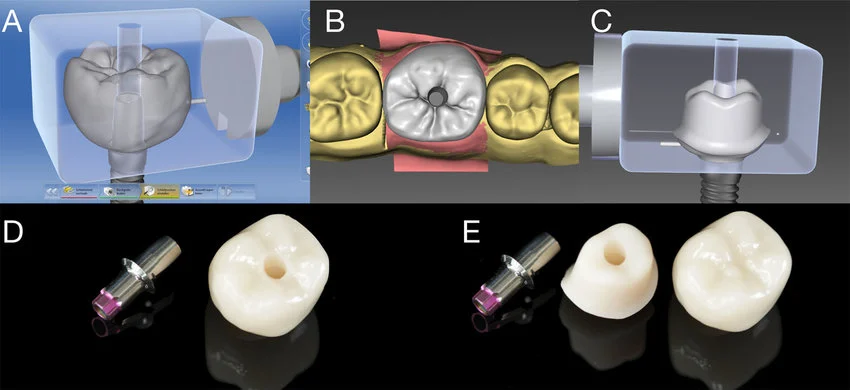
Two-piece hybrid abutment crowns—consisting of a milled zirconia superstructure bonded extraorally to a pre-machined titanium base (Ti-base)—combine the precision fit of a factory-machined metallic connection with the superior aesthetics and biocompatibility of zirconia.
Adhesive failure at the zirconia-titanium interface is an entirely avoidable laboratory error. Strict chemical conditioning is mandatory. The titanium bonding chimney must be airborne-particle abraded using 50µm aluminium oxide (Al₂O₃) at 1.5 to 2.0 bar pressure. The subgingival seating connection and anti-rotational indexing interface must be fully masked (using a laboratory analogue or protective silicone cap) during sandblasting; abrasive rounding of the mating lobes introduces rotational play and destroys the seal.
The internal bore of the sintered zirconia crown must likewise be sandblasted with 50µm Al₂O₃ at 1.5 bar, steam cleaned, and primed with an organophosphate monomer (10-MDP). A specialised anaerobic or dual-cure resin luting composite is applied to the Ti-base. Excess cement must be meticulously removed while in the gel state, and the entire subgingival transitional margin polished to a mirror glaze (Ra < 0.2µm) to promote stable hemidesmosomal soft-tissue attachment.
Where the crown has been designed from a digitally exported scan-body position rather than a physical die, the bonding jig or index used to seat the zirconia coping onto the Ti-base at the correct rotational orientation is just as critical as the chemistry — an out-of-index bond will faithfully reproduce whatever positional error was present in the original scan.
6. Passive Fit Verification & UK Work Ticket Compliance
For multi-unit implant frameworks and bridges, non-passive fit introduces permanent static strain into the bone-implant interface, accelerating crestal bone loss and screw fatigue. The technician must verify passive fit on the master cast using the Sheffield 1-Screw Test: tighten a single terminal screw; if any vertical lifting or rocking occurs at the opposite end of the framework, the bridge lacks passive fit and must be sectioned and re-indexed.
Where the case originated from an intraoral scan rather than a splinted open-tray impression, passive fit verification is more important, not less. Digital stitching error accumulates across the arch, so a full-arch framework designed entirely from an unverified IOS export should still be checked against a physical or 3D-printed verification jig before final milling wherever the span or implant count makes cumulative error a realistic risk.
Under the Medical Devices Regulations (MDR) enforced by the MHRA and GDC Standards Principle 4 (Clear Communication), dental laboratories hold a statutory duty to provide complete technical traceability. The laboratory delivery ticket is a legal medical device statement and must accompany every dispatch.
The technician must explicitly record: (1) The specific implant brand, connection geometry (e.g., Conical Index, Tri-Lobe, Internal Hex), and platform diameter (e.g., 3.5mm NP, 4.3mm RP); (2) Lot/batch numbers of all prosthetic components and luting agents; (3) The manufacturer-specified final clinical torque value (e.g., 30 Ncm, 35 Ncm, or 20 Ncm for ASC); and (4) The required driver tip geometry (e.g., 1.25mm Hex, Torx, Unigrip). Where the framework was digitally designed and either milled or additively manufactured, it is good practice to also record the manufacturing route and machine/printer identifier on the internal job card, even though this is not yet a strict MDR field, since it materially assists any future traceability investigation.